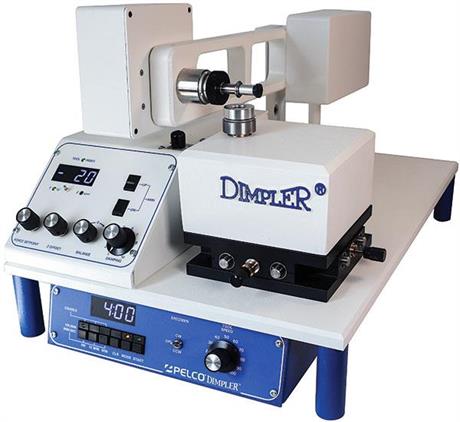
PELCO® Dimpler™
Precision thinning system for site-specific TEM analysis

The PELCO® Dimpler™ is the latest model in the evolution of the Dimpler line formerly available from South Bay Technology and provides Automated Precision Thinning of Specimens for TEM Analysis. It is a precision electro-mechanical metallographic lapping instrument that will continuously monitor and control dimpling parameters and accurately terminate at a preset specimen thickness. This breakthrough in electronic and mechanical integration has added repeatability and reliability to the dimpling process, as well as automation.
PELCO DIMPLER
PELCO® Dimpler™ precision specimen thinning for TEM
VIDEO ALIGNMENT MICROSCOPE
PELCO® Video Alignment Microscope
ADJUSTABLE PLATEN SET
Adjustable Platen Set
STANDARD TOOL SET FOR DIMPLING
Standard Tool Set for Dimpling 3mm samples for TEM
Several operating functions of the PELCO® Dimpler™ are built in to facilitate repeatable, usable dimpled samples:
Z Position
The Z position display indicates the termination set point and the dimple depth from the Non-Contact Sensor is analog to digital. The digital LED display in microns is updated once every tool revolution by the Tool Phase Detector at the same angular site. This negates any error due to tool run out, especially significant when using padded tools.
Termination
Four factors improve the termination accuracy:
- Non-Contact Position Sensor
- Tool Phase Sensor
- No external measuring device
- Magnetically coupled arm damping
The Non-Contact Position Sensor measures the location of the fulcrum arm which corresponds precisely to the thickness of the specimen. This sensor has an accuracy of better than one micron. Since it is non-contacting there are no detrimental effects on the action of the fulcrum arm. The reaction time of the sensor is fast enough to terminate the dimpling process the first time the Tool Phase Sensor indicates that the Z termination set point has been reached. Specimen thickness is measured directly on the PELCO®Dimpler™ with the tool surface as the measuring point. The dimple depth and the Z termination set point are measured with the same reference. This prevents any measurement error from being translated directly to a termination error.
Damping
Damping of the arm is accomplished by using position information from the Non-Contact Position Sensor, processing it and feeding it back to the arm motor, which controls the up/down force of the arm. The position sensor and the processing circuit is fast enough to actively dampen any vibration the arm may experience. Since the damping force is magnetically coupled to the arm there is no mechanical play in the system, allowing damping response on the sub-micrometer level. Damping is adjustable from zero damping to stiff damping.
Damping offers three significant attributes:
- Vibrations that can crack thin specimens are greatly reduced.
- Keeps tools round, negating excess impacts, providing more accurate Z position control.
- Tool gently contacts the specimen when the arm is lowered.
Automated Controls
Automated features make the dimpling process more repeatable and easy to use. Tools are raised and lowered at the touch of a button; dimpling force, damping force, fine balance, and Z offset (termination point) all are set from the front panel.
Once dimpling has begun no monitoring is necessary. After the initial specimen thickness has been measured, the specimen is mounted and the user simply selects a dimple depth and begins dimpling. The precise Z position of the tool/surface interface is continuously displayed while dimpling with any tool. When the selected dimple depth is reached the PELCO® Dimpler™ controls will automatically raise the arm then stop the tool rotation, specimen rotation, and clock timer.

Specimen Mounting
Specimens are mounted on optically smooth sapphire flats. Low thermal mass of the flat reduces mounting and dismounting times and the smooth surface allows the dimpled specimens to be gently slipped off. The hardness of sapphire limits damage if specimens are accidentally dimpled through due to operator error. The retainer ring which secures the sapphire flat also serves as a slurry reservoir. A specimen mounting jig is used for specimen centering during mounting. For off center dimples a special Eccentric Platen with a centering microscope is available.
Tools
Tools 1i and 2i are flatting tools and Tools 3i and 4i are dimpling tools. Tools 2i and 4i are supplied pre-padded with various types of metallographic polishing pad. In addition to saving the user the time of padding tools the machine formed padded tools have TIR (Total Indicator Reading) approaching Tools 1i and 3i Dimpling tool geometries have been improved, so that Dimpling Tools 3i and 4i will produce 380 micron diameter dimpled areas.
Working Interface
Research has indicated that Tools 2i and 4i have a working diameter within the nap of the pad. Whereas the ΔZ (change in Z offset value) between the specimen and the hard tool surface is virtually zero, the ΔZ between the “working interface” and the specimen is a function of dimpling force, tool speed, damping force, and pad compliance. After the dimpling force, tool speed, and damping force are selected, the working diameter will stabilize at the working interface of the pad. This working interface is monitored on the Z display and used as a reference location from which a specimen is to be dimpled further. A user can control the dimple depth and removal with a virtually seamless padded tool. This position control allows the dimpling force to approach zero within 1 gram increments.

PELCO® Dimpler™ Specifications
|
|||||||||||||||||||||||||||||||||||||||||||||||||||||||||
